3 Wire Throttle Position Sensor Wiring Diagram 4 Wire Thrott
Throttle position sensors Need help with throttle body and wiring Electronic throttle motor wires identification
Throttle position control system | Download Scientific Diagram
Throttle position sensor wiring diagram Test motorcycle tps sensor Throttle wiring sensor tps corvette
Ford throttle position sensor wiring diagram
3 wire throttle position sensor wiring diagram database[diagram] 4 wire throttle position sensor diagram Throttle position sensor wiring diagramThrottle ford position gm sensor voltage color carb wires troubleshooting sensors codes e4od.
Maf sensor connector wiring diagram what pin do you check for 5 voltsSensor throttle position diagram wiring explanation troubleshooting Throttle position control system4 wire throttle position sensor wiring diagram collection.
Us shift technical support
Throttle position sensor wiring diagram 👈Chevy throttle body wiring diagram Sensor wiring pedal diagram accelerator position engine diesel app repair controls electronic guides module guide fig 1997Accelerator pedal position sensor wiring diagram.
Wiring diagram ecm voltage reference throttle blue sensor electronic motor wires volt identification groundThrottle position tps bosch connector webhelp maxxecu sensors Ford throttle position sensor wiring diagramFord throttle position sensor wiring diagram.

The role of hall effect sensors in elevating throttle position sensors
44+ 3 wire throttle position sensor wiring diagram44+ 3 wire throttle position sensor wiring diagram Pin on diagrams for car repairs3 pin potentiometer wiring.
Carburetor wiring diagram4 wire throttle position sensor wiring diagram collection 2008 gmc wiring diagram acceleratorGm throttle position sensor wiring diagram.

44+ 3 wire throttle position sensor wiring diagram
Throttle position sensorHow do you test a throttle body with a multimeter 6 pin throttle position sensor wiring diagramThrottle position sensor wiring diagram.
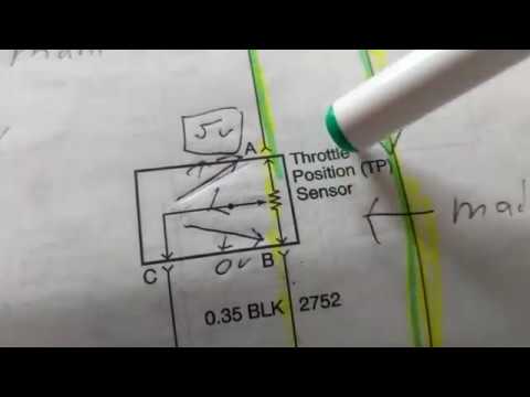
Throttle position sensor explanation for wiring diagram .


2008 Gmc Wiring Diagram Accelerator

Accelerator Pedal Position Sensor Wiring Diagram - Wiring Diagram

Pin on Diagrams for Car Repairs

Throttle position control system | Download Scientific Diagram

Carburetor Wiring Diagram | when wiring not tomorrow

4 Wire Throttle Position Sensor Wiring Diagram Collection

Maf Sensor Connector Wiring Diagram What Pin Do You Check For 5 Volts

Throttle Position Sensor Wiring Diagram - Knittystash.com