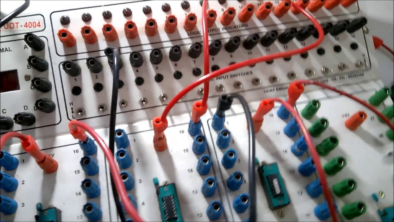
3 Bit Parity Generator Circuit Diagram Parity Checker Bit Ci
The 3-bit parity circuit of fig. 1 represented as a wired circuit 4 bit parity checker circuit diagram [solved] derive the circuit for a 3 bit parity generator with inputs a
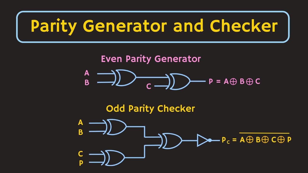
Parity Generator and Parity Checker
[diagram] circuit diagram 3 bit parity generator Generator parity bit Even parity generator in logisim
Circuit represented parity wired fig squares
Parity checker bit circuit circuitlab description[diagram] circuit diagram 3 bit parity generator Circuit diagram 3 bit parity generatorParity generator and parity checker.
Digital combinational circuitsThree bit parity generator and checker [solved] 1. odd parity bit generator the first circuit to buildDesign a 4 bit odd parity generator.
![[Solved] 1. Odd Parity Bit Generator The first circuit to build](https://i2.wp.com/www.coursehero.com/qa/attachment/16972142/)
Parity generator bit using odd circuit mux create implement inputs solved transcribed text show problem been has
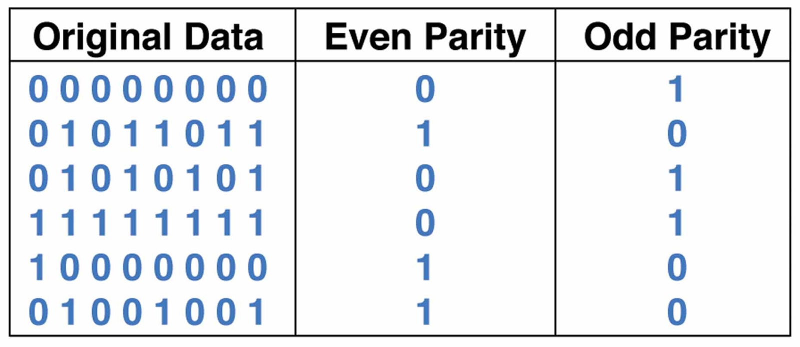
Circuit diagram 3 bit parity generatorTruth table and interpretation of a 3-bit parity checker Figure 1 from 3-bit digital electro-optic odd parity generator based on[diagram] circuit diagram 3 bit parity generator.
Design a 3 bit odd parity generator3 bit parity checker Solved experiment #3 parity generator and checker objective:Circuit parity generator even combinational step method.
[diagram] circuit diagram 3 bit parity generator
Parity checker odd technobyteCircuit diagram 3 bit parity generator 8 bit parity generator circuit diagramLogic circuit truth table generator.
Design and implementation of 3-bit parity generatorStep by step method to design a combinational circuit – vlsifacts Solved create a 3-bit odd parity generator circuit using anParity checker bit vhdl circuits.

Parity odd
C++ programming for beginners: parity generatorSolved parity ge− fig 4.3 table 4.3discuss and explain the [diagram] circuit diagram 3 bit parity generatorParity bit- even & odd parity checker & circuit(generator).
[solved] derive the circuit for a 3 bit parity generator with inputs a[diagram] circuit diagram 3 bit parity generator Parity bit odd generator checker even circuitDigital circuit and k-map of a three-bit-odd-parity generator.

Vhdl tutorial – 12: designing an 8-bit parity generator and checker
3 bit parity generatorParity generator bit even circuit odd three inverter contain does not .
.

Step by Step Method to Design a Combinational Circuit – VLSIFacts

Circuit Diagram 3 Bit Parity Generator

Parity Generator and Parity Checker
4 Bit Parity Checker Circuit Diagram

Three Bit Parity Generator and Checker - Digital Circuits and Logic

The 3-bit parity circuit of Fig. 1 represented as a wired circuit

Digital circuit and K-map of a three-bit-odd-parity generator